

An alternative approach to CAD building or upgrading
One can build all CAD work directly with prior and indissoluble linkage between each graphic element and descriptive data. That means, when any graphic primitive is created in such CAD drawing, the corresponding entry is attached to the corresponding "table". The latter may be set according to user’s needs and is intended to the input and storage of the descriptive data of drawing objects, etc.
The software with such work principles for graphic data drawing and analysis exists even longer than CAD itself. The examples of such software are all classic and not very classic GIS. It must be said that drawing is rather elective for GIS, so the process of the required data tables creation for graphic objects properties definition is not quick while it is much more difficult to draw. That is why it is necessary to make drawing as easy in the hypothetical CAD as it is.
Now: while drawing, we call somehow common insert command of the first graphic element (with button or commandline). Instead, we can drop a block from the design center, copy from another file, etc. Anyway, we draw standard conventional primitive with the desired graphic properties. Say, a line in layer “0” or a block in any manner or text, etc. Draw, insert just as we do it now in CAD.
But, at the same time:
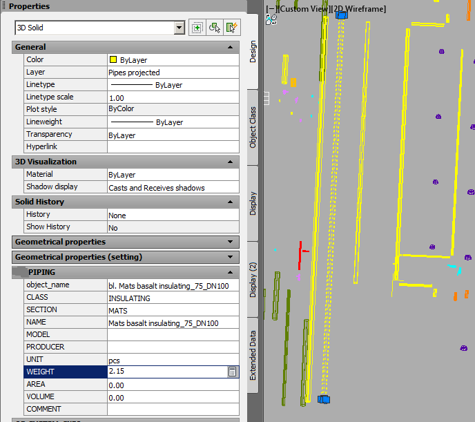
- A "table" with the temporary name like "table_0" is created, where an "entry" linked to the element is added. There is only one “field” in the "table" for now – for temporary object name like "line_0". The names "table", "field" (hereinafter - without quotes) and the field value are displayed in the Properties window.
- “line_0” appears in the special window Drawing objects menu. This window is kind of Tool Palettes window, but is automatically populated as drawing objects with unique sets of graphic and descriptive parameters are added.
- A text file of simple structure describing drawing objects is created – as it is done when Tool palettes are created – but not so unclear as their XML. The name is equal to the drawing name. Object description and its basic parameters (name, primitive type, layer, color, width, etc. required) as well as object table description (name, fields description, acceptable field values) are written into that file.
Object data tables can be created with basic AutoCAD’s extended data – XRecords, etc. In other words, there is nothing to be developed and added to the existing capabilities. Graphic elements with extended data are exactly the same as those without it. They do not cause any difficulties for usual workflow.
Accordingly, when drawing each successive element (with buttons, commands, etc.) the objects menu is appended – "Line_1", "Line_2", "Text_34", "Block_17"…
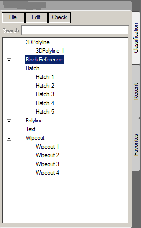
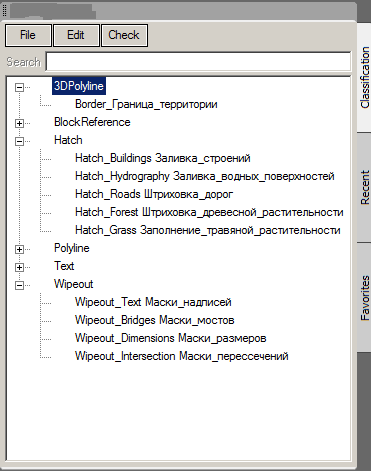
The user is given the opportunity to edit objects’ names substituting with human-transparent ones. For example, instead of "Line_2" – "Wall Line", instead of "Polyline_6" – "Road Axis ", instead of "Block_22" – "Daylight Lamp", instead of "Text_1" - "Name Label", etc.
Furthermore, the users are given the opportunity to add proper descriptive data fields as well as to edit all the parameters in object descriptions – layer, color, etc.
Thus, simultaneously with drawing creation, the drawing object types menu as well as the file with their description are created and automatically updated. Eventually, the description of all object types in the drawing as well as the corresponding descriptive data are created.
Thanks to the objects menu, it is possible to draw not only with usual commands, but also with the menu – with proper graphic properties and data table defined. Almost like drawing with Tool palettes. But the object menu is to be made more convenient – as a tree-menu. In other words, with the ability to group objects into classes, to collapse and expand object lists if needed. The description of the classes and well as object grouping are also presented in the definition file.
Finished objects definition files can be a description of drawing standards, can be given to the co-authors and other users that will make it possible to draw faster and meet the required standard. That is, finished objects definition files can be loaded before drawing that will ensure drawing in one standard to all co-authors of one project, one organization or one task.
Descriptive data fields can be used for any necessary object information – size, position, features, properties, etc. According to this data, one can fulfill the desired model analysis, create reports, lists, etc.
Descriptive data field may be used for script names that should be applied for proper object type, to describe the events and conditions under which the scripts should be applied, to describe object types for interaction with which the scripts must be applied.
Naturally, in such CAD the user must be provided with an appropriate basic set of features to work with tables and data fields, data analysis, the analysis of descriptive data together with the objects’ geometry, etc.
Numerous advantages of such an approach are largely described in the previous articles – “Speed up drawing...”, “OD/DB...” but they illustrated the way of CAD add-on. Of course, building CAD on this approach is more essential and efficient. There are a number of qualitative changes in CAD workflow in this case. These changes are not only in speed, the degree of standards conformity, numerous opportunities to analyze and calculate, etc. The overall approach to the process of drawing is changing –user attention is transferred from drawing tools to the very subject of the drawing, modeling.
Thus, CAD evolves from mainly graphic tool to create drawings into the tool to create "information models" (this quotes are put not to diminish such models, but to represent the vagueness of the term). Given all the existing conventional capabilities, CAD becomes quite an information system. Although not in the sense of special BIM systems, although too static as compared to these systems, but becomes truly an information system. In other words, a system intended to the computer, software data analysis in all aspects. Furthermore, not less but more convenient for drawing as compared to existing CAD.
UPD:
About data format. Encouraging real example in AutoCAD Map 3D – SDF format. The data of this format is read and processed by AutoCAD. Given that the number of objects can reach many millions, the performance is quite satisfactory, without apparent lags even while multiuser work. Of course, there is an exchange between DWG and SDF in AutoCAD Map 3D.
16.07.2016
Alexander Sharov
Translation: Sheviakov Sergei
